This invention is dedicated to the public
Original publication date: 22 Jul 2018
Dmitriy Levchenkov, arithmechanics.com
One of the most reliable ways to diagnose a parasitic current draw in an electric system is to check current flowing through each fuse without taking them out. This is possible because most fuses have accessible terminals and so voltage drop between them can be measured. However, voltage drop alone does not tell the current value without knowing fuse resistance.
There are two approaches practiced:
- Record the voltage drop and then use a look-up table (LUT) for fuse type and value to determine the amperage.
- Set the fuse type and value in a device such as AmpHound (tm) that will do calculations for you.
The problem is that, with modern cars having several dozens of fuses, the process of looking up (if using LUT) or selecting (if using AmpHound) fuse types and values can get lengthy. Ideally, an electronic device should perform some experiments and determine fuse resistance automatically.
This invention describes such a device. The main challenge, however, is to accurately measure small voltages and process them without losing precision.
It is claimed that:
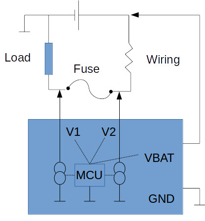
- A device (see Fig. 1) consisting of + and - battery leads, two probes, voltmeter circuitry capable of accurately measuring voltages between the probes and leads, current sink circuitry capable of loading each of the probes with specified current, and a processor (MCU), is capable of determining the fuse resistance as long as non-zero current flows through the fuse and creates voltage drops across the fuse, wiring, and the load.
- Such a device would be able to also determine faults such as a blown fuse, issues with upstream wiring, battery, and load.
- Further, the results of fuse resistance measurement can then be used to compute real-time current through the fuse, which can be shown or graphed on a display and/or be sent to a digital-analog converter (DAC) to which an oscilloscope is connected.

Fig. 1